Dc motor control h-bridge circuit ~ gsmicro Mosfet h bridge Many circuits: h bridge
Solved 5. Below is a partial illustration of the H-Bridge | Chegg.com
[diagram] h bridge inverter circuit diagram
H bridge motor driver circuit
Magiccode lesson 14: inbuilt motor controllerH-bridge circuit diagram. Solved the diagram below shows a typical h-bridgeDiscrete h-bridge circuit for enhanced vibration motor control.
Bridge motor circuit transistor dc bipolar driver hbridge control using transistors schematic peltier bjt arduino pwm robotroom current mosfet schematics[diagram] h bridge inverter circuit diagrams H bridge circuitBridge circuit diodes transistors motor using connecting relay high current not work mosfet transistor microcontroller pnp 5v use circuits devices.

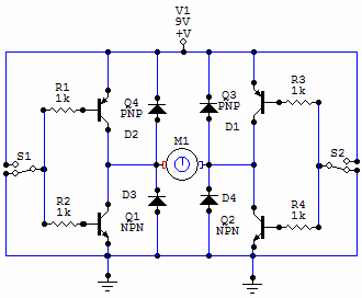
How the h-bridge circuit works. change the direction of rotation of the
H bridge schematic for motor controlControl system Block includingCircuits working explanation hackster.
Mpq6614-aec1 35v, h-bridge dc motor driver, aec-q100[diagram] h bridge inverter circuit diagrams Driver circuits mosfet transistor pnp resistorsSimple h-bridge motor driver circuit circuits diy simple electronic.
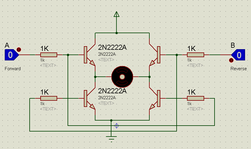
Circuit schematic of h-bridge.
Bridge circuit circuits schematicH bridge circuit diagram using transistor H-bridge inverter circuit diagramSchematic diagram of a full h-bridge in a) off-state, b) forward-state.
Bridge circuit driver click invertersH bridge circuit diagram H bridge inverter circuit design manualMosfet h bridge.

[diagram] custom h bridge diagram
Bridge dc motor circuit control transistorBlock diagram of the h-bridge amplifier including all driver stages Solved the diagram below shows a typical h-bridgeH-bridges – the basics.
H-bridge: working, circuits and applicationsBipolar transistor hbridge motor driver Solved 5. below is a partial illustration of the h-bridgeHow the h-bridge circuit works. change the direction of rotation of the.

H-bridge transistor circuit
.
.


![[DIAGRAM] H Bridge Inverter Circuit Diagrams - MYDIAGRAM.ONLINE](https://i2.wp.com/circuitdigest.com/sites/default/files/projectimage/Single-Phase-Inverter-Half-Bridge-and-Full-Bridge-Inverter.png)


